Walk-in Air Flow Patterns
Bemco Integral and Modular Walk-in and Drive-in Environmental rooms are available with a number of different standard air flow patterns. Depending on the chamber design, air flow can be combined with temperature, humidity, altitude and hyperbaric (below site altitude) conditioning systems. These air flow patterns are created by using axial and tubeaxial fans, forward and backward curved blowers, and large propeller fans combined with diffusers, baffles, air straightening devices, and ducts.
Air flow volumes are optimized to the intended use and vary from a few hundred cubic feet per minute to hundreds of thousands of cubic feet per minute when air flow speed simulation is required. When very high airflow speeds are required, custom configurations are often recommended. Air movers are available with either fixed speed or variable speed drives of various types suited to their horsepower. Typical drive motors vary from fractional units to approximately 500 horsepower.
Some of the standard airflow patterns available include:
Pattern |
Type | Advantages |
Disadvantages |
| Side Plenum |
Circular |
Lowest cost, most compact |
Blocked by larger loads, uniformity |
Ceiling Split |
Dual Circular |
Lower cost, relatively
compact |
Blocked by tall load, condensation |
Diagonal |
Diagonal Circular |
Large loads do not block |
Flow eddies in upper corner |
Ceiling Plenum |
Vertical Circular |
Lower velocity, quieter |
Heat transfer on small
loads |
Horizontal |
Horizontal Circular |
Test load flexibility, smooth
flow |
Cost, more floor space needed |
| Vertical | Vertical Laminar |
Computer floor, smooth flow |
Cost, floor recess for door |
Side Plenum Flow:
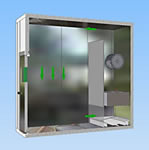 Together
with Ceiling Split Flow, the least expensive air flow pattern.
Air leaves the conditioning system, located on one wall of the
chamber at the top near the ceiling and returns to the conditioning
system near the floor on the same wall.
An economical configuration for general purpose use, air circulation systems of this type are limited in their ability to move air over great distances and generate slightly higher noise levels than other alternatives, with the exception of Ceiling Split Flow.
Ceiling Split Flow:
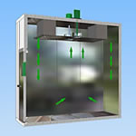 The
smallest floor space requirement of all conditioning system patterns,
this type of circulation is best suited to processes where the
load sits in a central location on the floor of the workspace.
Generating the highest noise level of all systems, taller loads near the walls have a tendency to cause short cycling on one or both sides of the air loop. Drain pans for cooling coils must be carefully designed to prevent dripping from the roof. Not recommended for humidity systems.
Diagonal Flow:
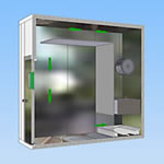 Similar
to Side Plenum Flow except a ceiling duct is provided so that
air leaves the conditioning system near the top on the wall opposite
the conditioning system.
A good solution when taller or larger loads are present in the workspace that might block and short circuit the flow pattern on a Side Plenum System.
An alternate to Side Plenum Flow that compensates for long air paths. Recommended when the selected chamber is longer than 15 feet.
Ceiling Plenum Flow:
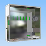 Similar
to Side Plenum Flow except a pressurized, perforated air distribution
plenum is provided to evenly distribute air discharge from the
chamber ceiling.
On larger chambers, dampers or screens are provided to allow flow balancing to compensate for distance from the conditioning system.
A good medium cost solution for a fully or tightly loaded chamber. Because discharge velocities are lower, this system is relatively quiet.
Horizontal Flow:
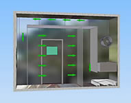 The
most expensive solution using the largest amount of floor space,
this system has both a pressurized perforated air distribution
plenum on the opposite wall from the conditioning system and another
perforated air suction plenum on the same side as the conditioning
equipment.
This configuration gives excellent air flow uniformity and balanced air velocity in the test area.
It is not a good selection if test objects are placed to block air flow.
Vertical Flow:
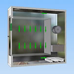 A
moderately expensive solution, this system has both a pressurized
ceiling plenum and a perforated floor. Not shown in the illustration,
the floor panels are reinforced for loading and are removable.
This pattern also provides excellent air flow uniformity and balanced air velocity in the test area.
It allows wiring or piping to be run under the floor. Its primary disadvantage is the requirement for a raised door. Typically, the chamber is recessed into the floor.
Heat Transfer vs Air Flow:
How effectively a product tracks the internal chamber conditions is a function of air temperature uniformity, air flow volume, air velocity uniformity, and test item configuration.
The heat transfer rate on the surface of a test object varies with the temperature difference between the air and the object, the ambient air or nitrogen pressure, and the average flow rate over the surface of the object.
A product’s exposed surface area, size, shape, mass, and material of construction determine how well it responds to a forcing temperature change. For every application, Bemco analyzes your test object and recommends the best combination of air flow pattern, conditioning systems, and controls. Often, the ideal solution involves not only a well matched air flow pattern but an advanced, PLC or multi-channel digital process control system as well as an adjustable flow air system. Bemco offers variable speed drive axial fans and blowers integrated with the air systems described above as a standard option.


